

Azimuth Window
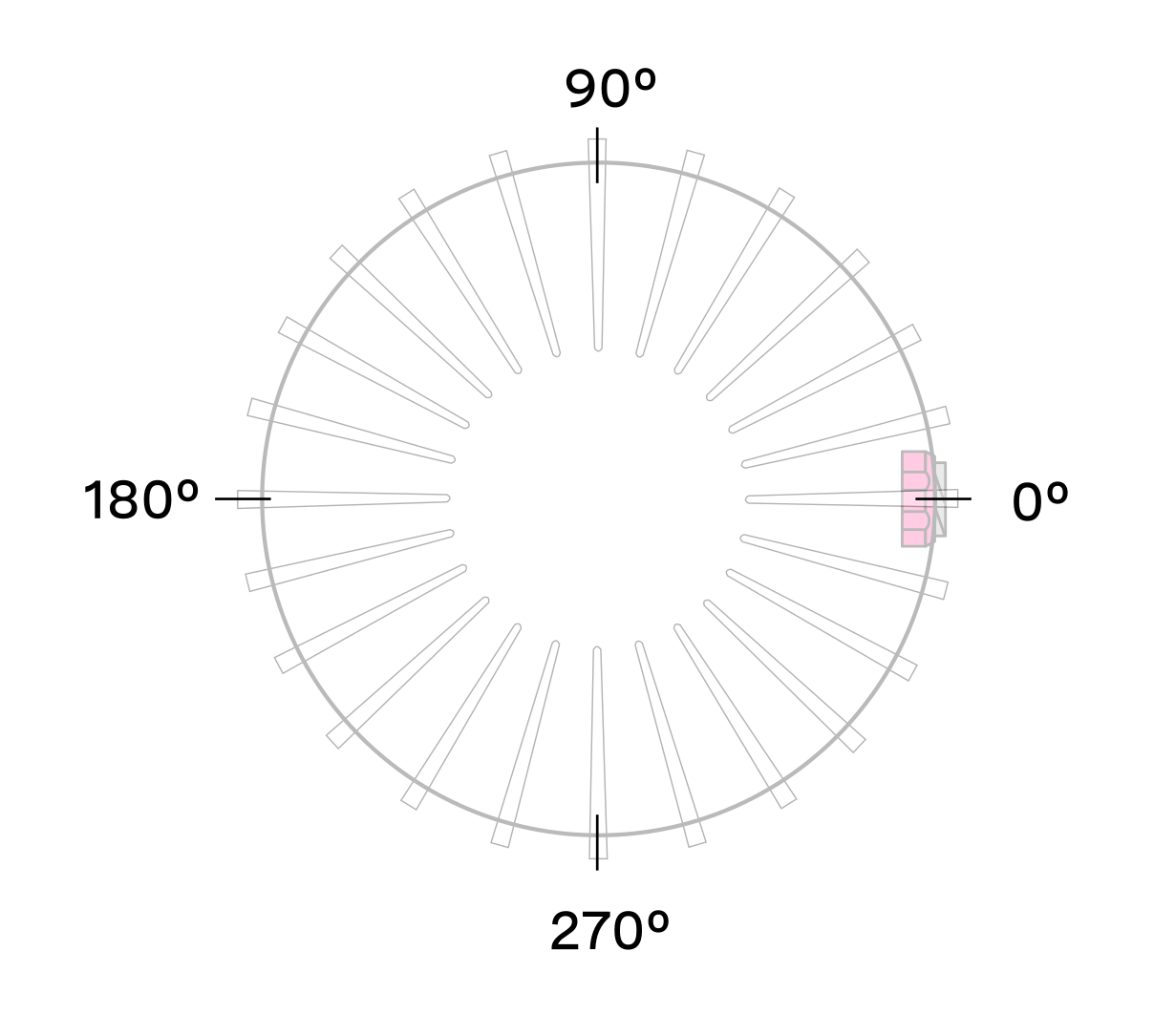
The azimuth window limits UDP lidar output to a configurable region of interest, defined by a minimum and maximum bound in millidegrees. Angles in the Lidar Coordinate Frame increment counterclockwise when viewed from above:
- 0° towards the external connector
- 90° a quarter turn counterclockwise from the connector
- 180° opposite the connector
- 270° three quarter turns counterclockwise from the connector
Reducing the azimuth window lowers average output data rate but does not affect peak data rate. Lasers continue to fire outside the window, so power consumption and thermals are unaffected.
Expected Sensor Behavior
The sensor rounds input bounds to the nearest Measurement Block IDs, then uses those ID-based bounds to mask Measurement Blocks in lidar packets. Packets containing only masked blocks are suppressed. The two bookending packets in each frame may be partially masked; the Measurement Block Status field identifies valid versus masked blocks in those packets. See Sensor Data for packet format details.
Staggered beam azimuth angles produce jagged edges at the window boundaries. Set slightly wider bounds to push jagged edges outside the desired region. The correct bounds can be found by trial-and-error or calculated from the queryable beam azimuth angles.
Azimuth Window Examples
Use the sensor configuration endpoint to set azimuth_window.
Default settings of 360° window:
Set a region of interest between 0° to 180°:
Set a region of interest between 270° to 90° with 180° field of view:
Set a region of interest 90° to 270° with 180° field of view:
Set a region of interest between 0° to 90° with 90° field of view:
Set a region of interest 90° to 360° with 270° field of view:
Azimuth Laser Masking
When a limited azimuth window is set, the sensor automatically disables lasers outside that window. This reduces thermal load and can improve sustained performance at elevated temperatures.