

Zone Monitor
Zone Monitor provides real-time point cloud monitoring on the sensor without external processing. It monitors user-defined 3D volumes, called zones, and reports whether each zone meets its configured trigger condition.
A zone can be defined from an STL mesh rendered by the sensor or from a pre-rendered Zone Render Binary (.zrb) bounds map. Zones are organized into a Zone Set Configuration, which also defines metadata such as coordinate frames, the sensor-to-body transform, power-on live zones, and trigger thresholds.
The sensor can actively monitor up to 16 live zones at a time, selected from an active set of up to 128 zones. Live zone updates are sent with small UDP packets that contain zone status and statistics. When live zones are changed through the API, updates typically appear in one or two frames, depending on whether the newly selected zones are already cached in DRAM or must be loaded from disk.
Getting Started
Zone Monitor supports up to 128 3D zones of any shape or size, with the ability to actively monitor 16 zones simultaneously.
Defining Zones
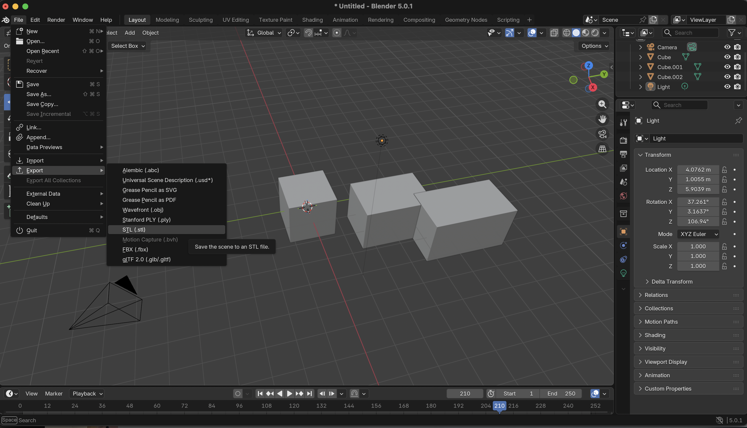
Each zone is defined as a 3D volume in STL format. These can be authored using tools like Blender or other 3D modeling software capable of exporting STL meshes.
For programmatic zone generation via Python, see the SDK documentation.
Deployment Workflow
- Create one or more
.stlfiles defining your zone volumes. - Create a
metadata.jsonfile describing zone configuration (thresholds, coordinate frames, etc.). - Package the STL files and metadata into a single
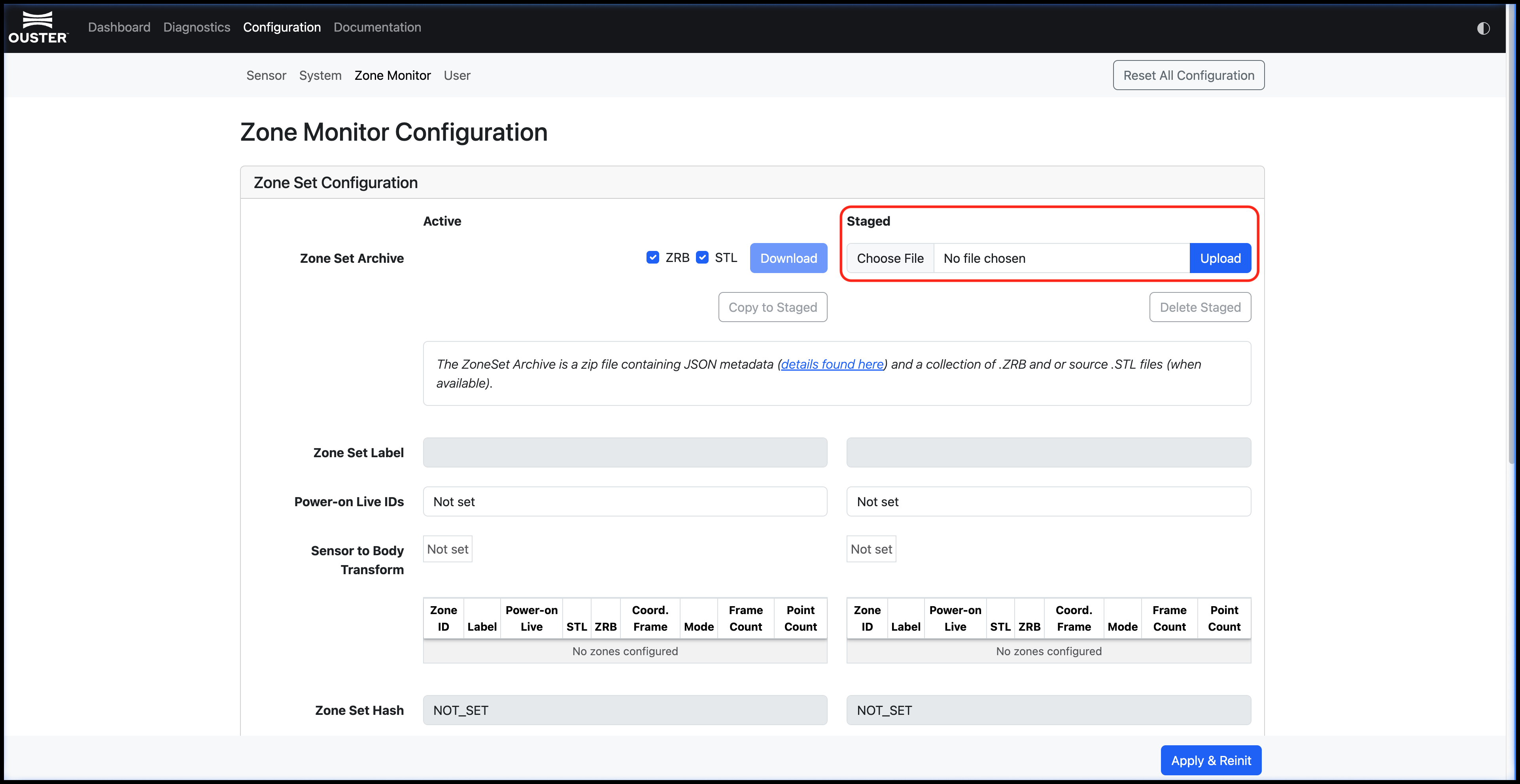
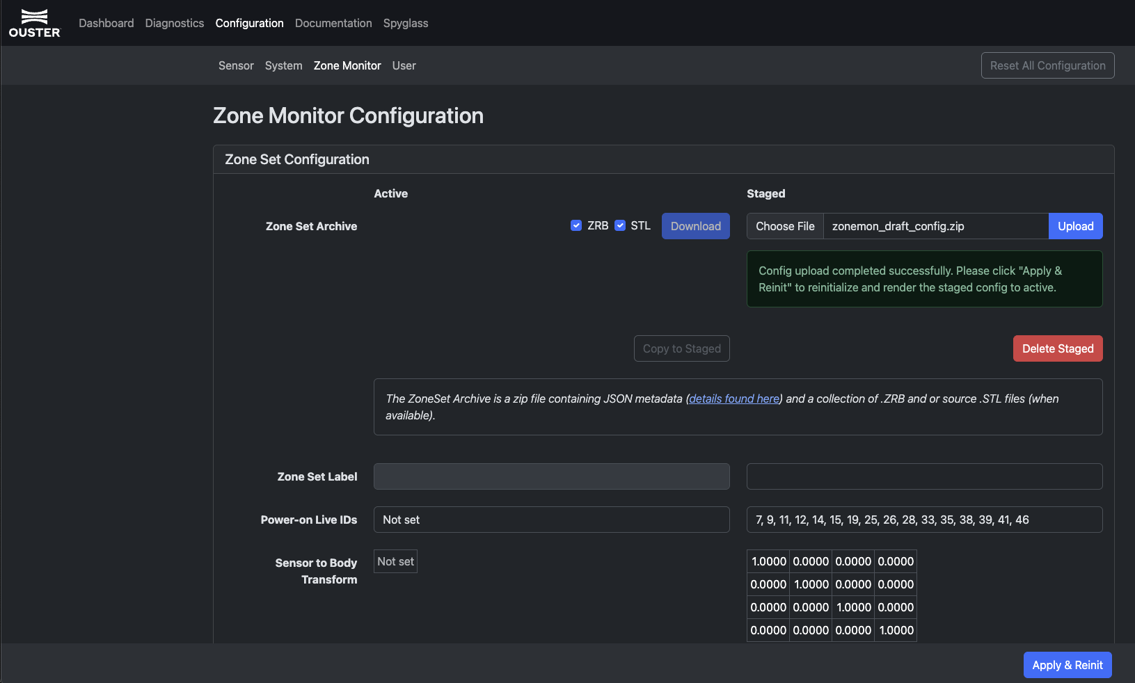
.ziparchive. - Upload the
.zipfile to the Zone Monitoring configuration page in the sensor web UI. - Click Apply and Reinit.
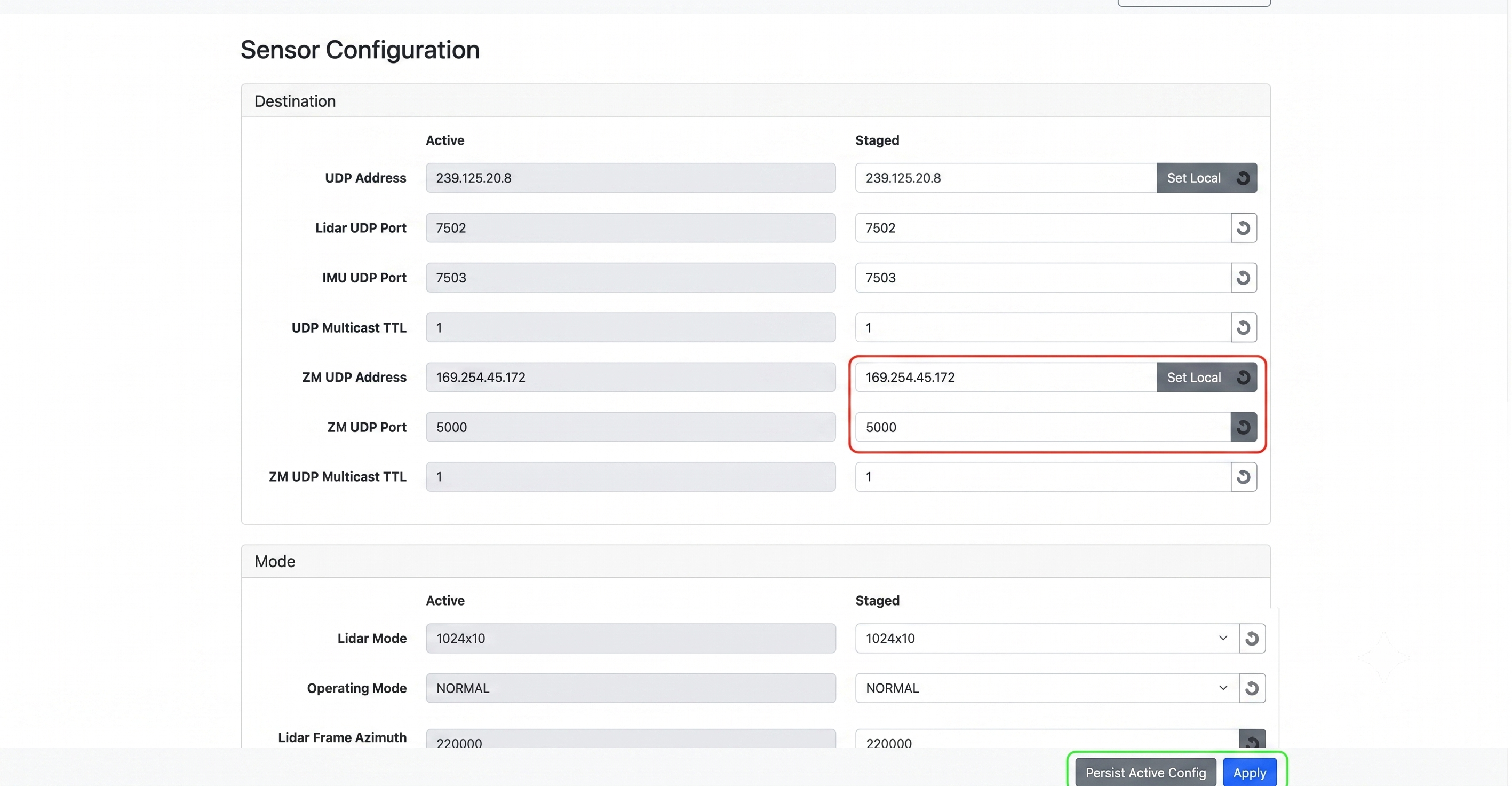
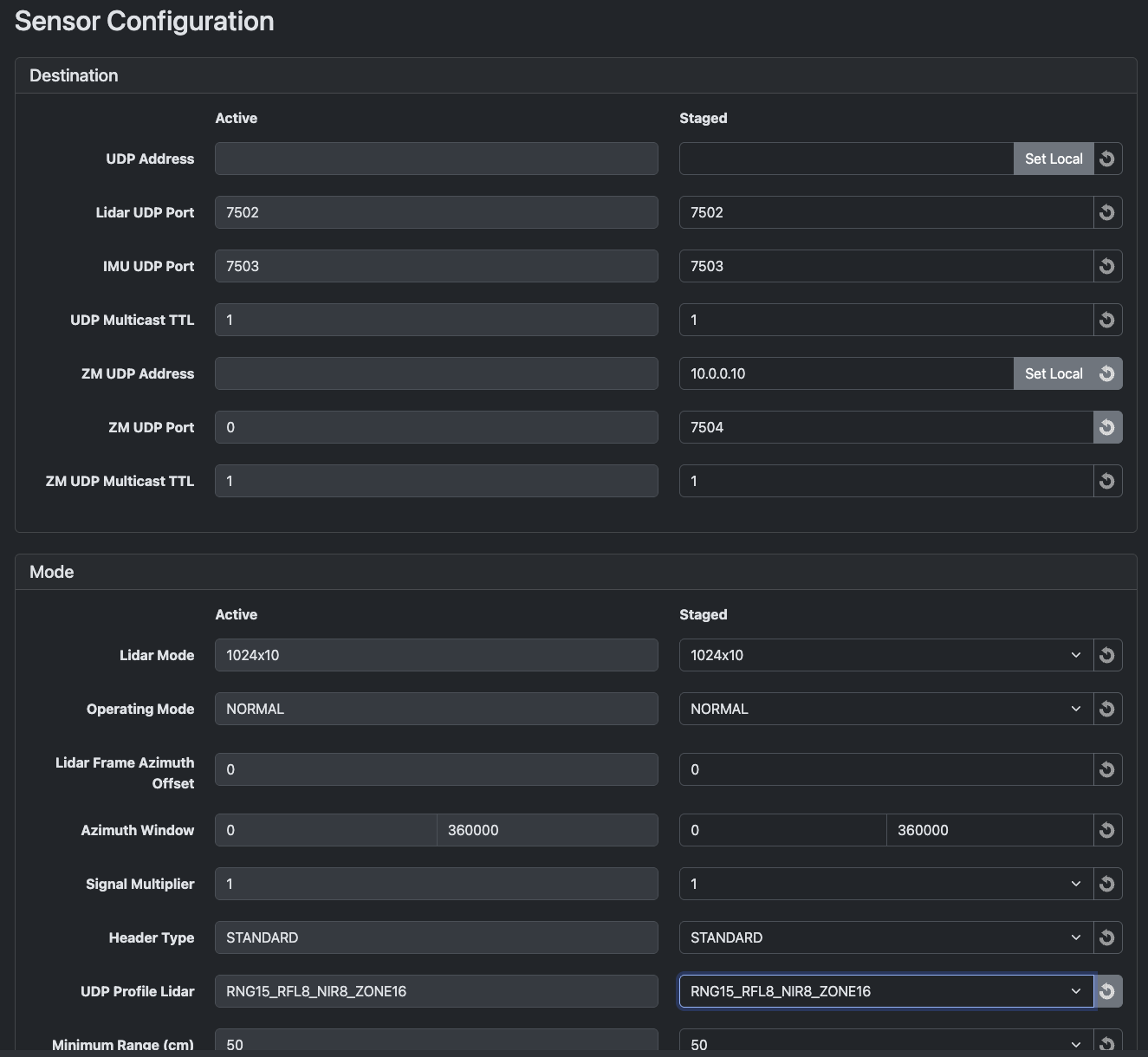
- Navigate to the Sensor page in the Configuration tab and set the ZM UDP Port to any non-zero value to enable Zone Monitor data transmission.
Zone Monitor API Commands
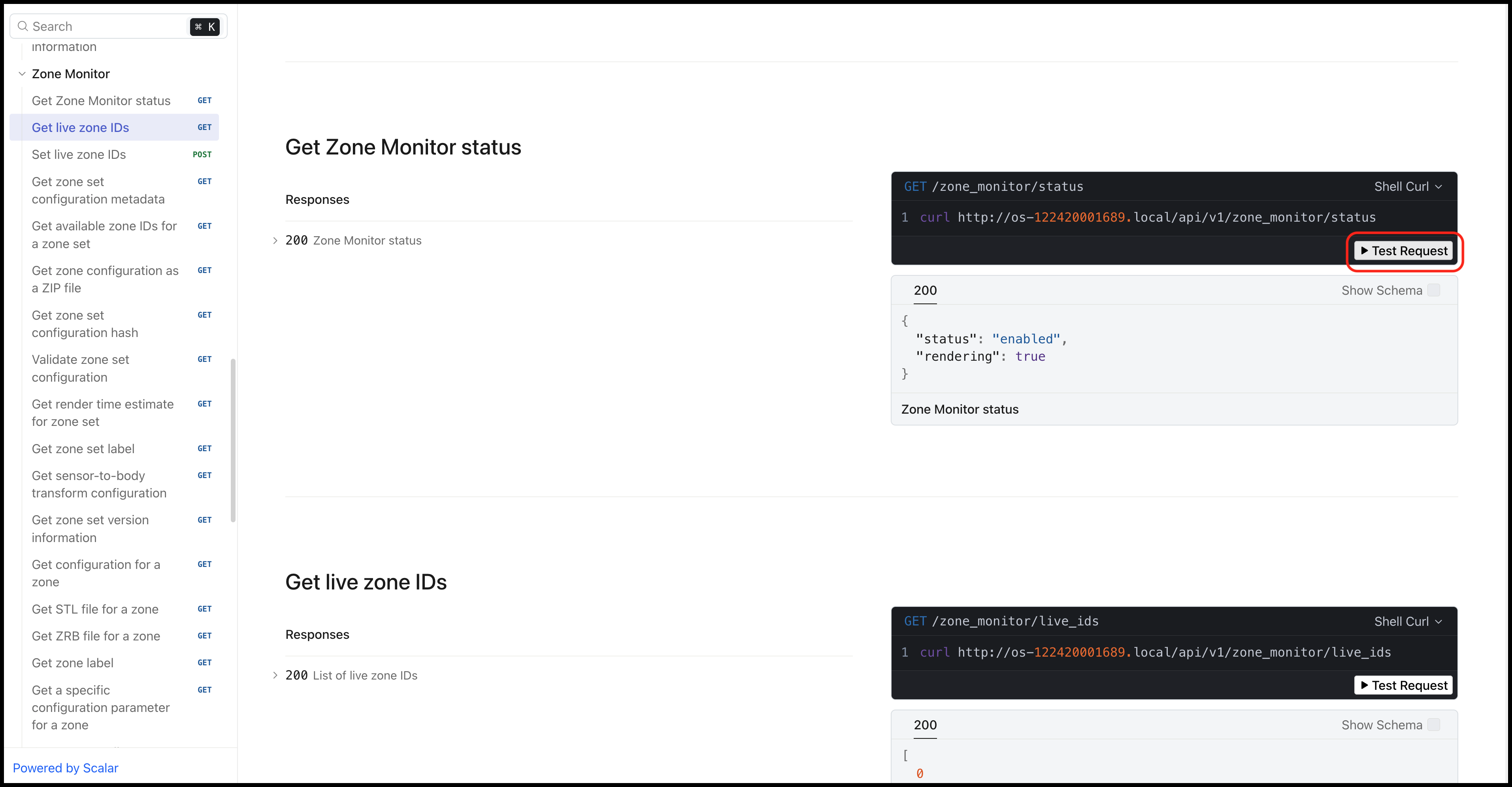
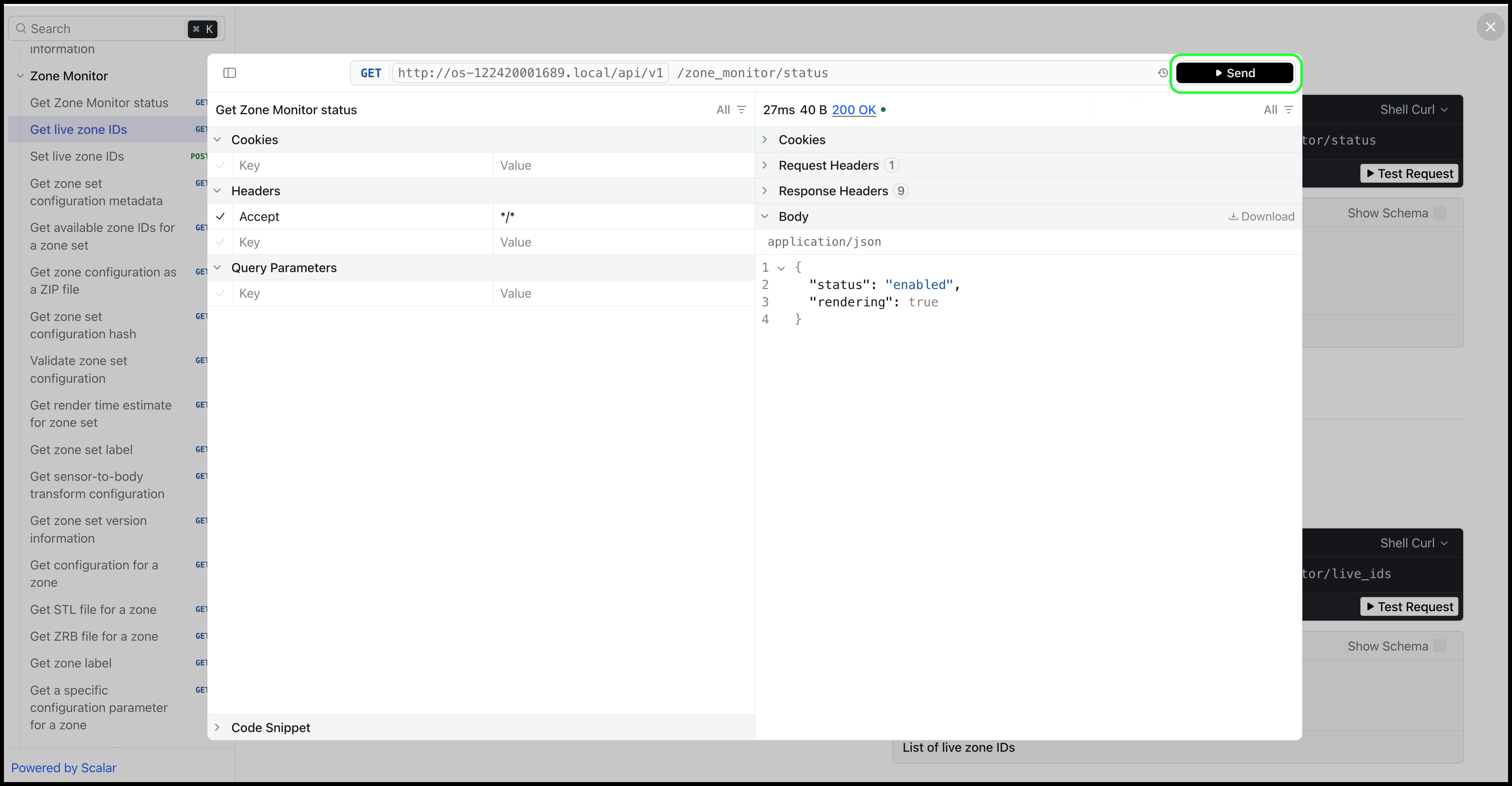
Once Zone Monitor is enabled and active, you can send API requests to the sensor through the Documentation page on the sensor dashboard. Available operations include:
Get Zone Monitor Status — Retrieves the current state of Zone Monitor, including whether it is enabled and which zones are active.
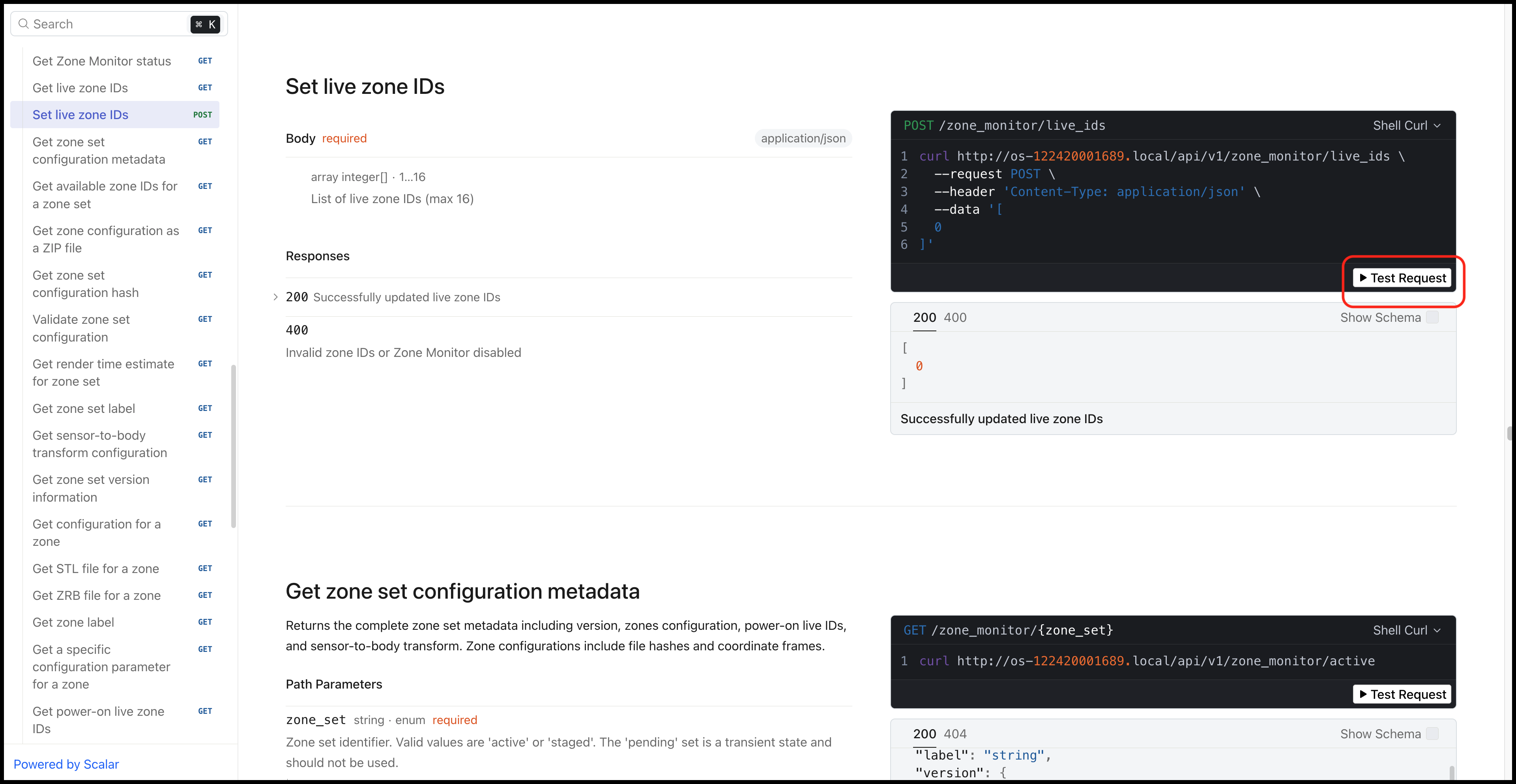
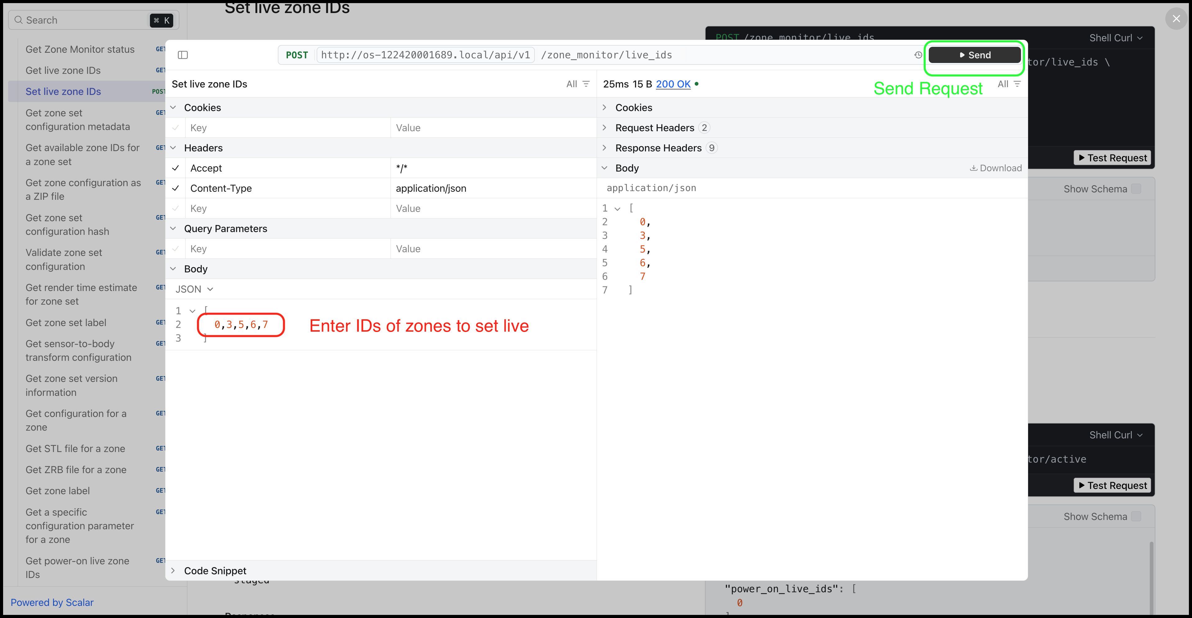
Set Live IDs — Selects which zone IDs are actively monitored. Up to 16 zones can be live at a time. After sending the request, the sensor begins monitoring only the specified zone IDs.
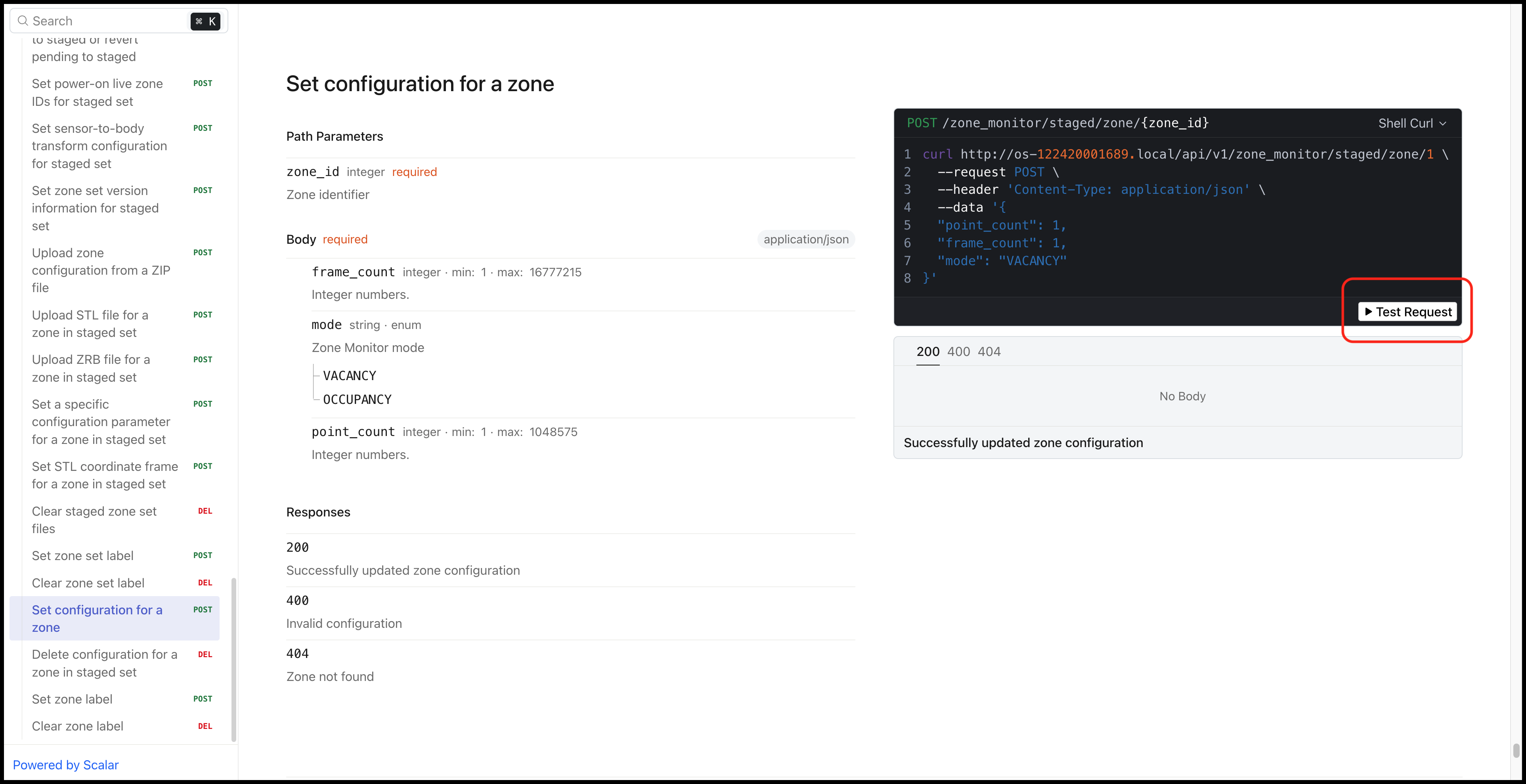
Set Zone Configuration — Configures individual zone parameters including trigger type (occupancy or vacancy), point count threshold, and frame count threshold. These parameters can only be changed on the staged Zone Configuration and then applied via the Apply & Reinit button.
For zone visualization and advanced configuration workflows, see the SDK documentation.
Zone Set Configuration
A Zone Set Configuration consists of:
- A JSON metadata file that describes zones, thresholds, coordinate frames, defaults, and checksums.
- A collection of zone files, either source STL meshes or pre-rendered
.zrbfiles.
Upload the configuration as a single ZIP archive through the web UI, or upload the individual files through the HTTP API. After upload, the sensor validates the configuration and reports errors before applying invalid inputs.
Configuration Flow
- Upload the Zone Set Configuration and apply it.
- The sensor validates the uploaded Zone Set Configuration.
- If validation fails, the sensor refuses to apply the configuration and reports an error.
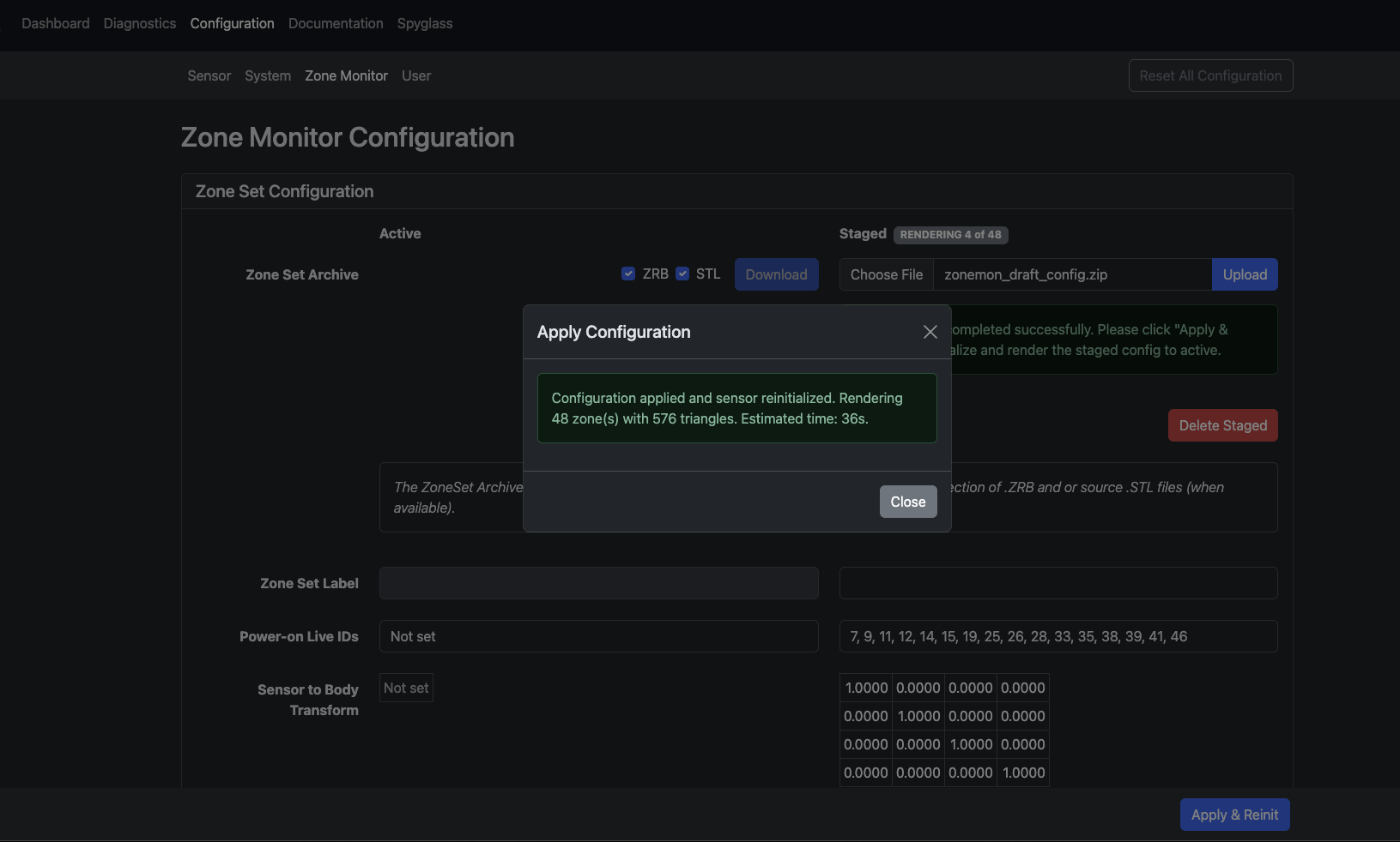
- If validation passes, the Zone Set is staged and the sensor reinitializes.
- After reinitialization, the sensor checks the Zone Set’s current state:
- If zones are STL-defined:
- ZRBs are reused when they are present and current for the sensor and its configuration.
- Missing or outdated ZRBs are rendered from scratch.
- If zones are ZRB-defined:
- Contents are validated against known sensor properties and the current configuration.
- If zones are STL-defined:
- The validated and rendered Zone Set replaces the Live Set, and Zone Monitor is enabled.
Rendering time depends on STL complexity, field-of-view coverage, and configured lidar resolution.
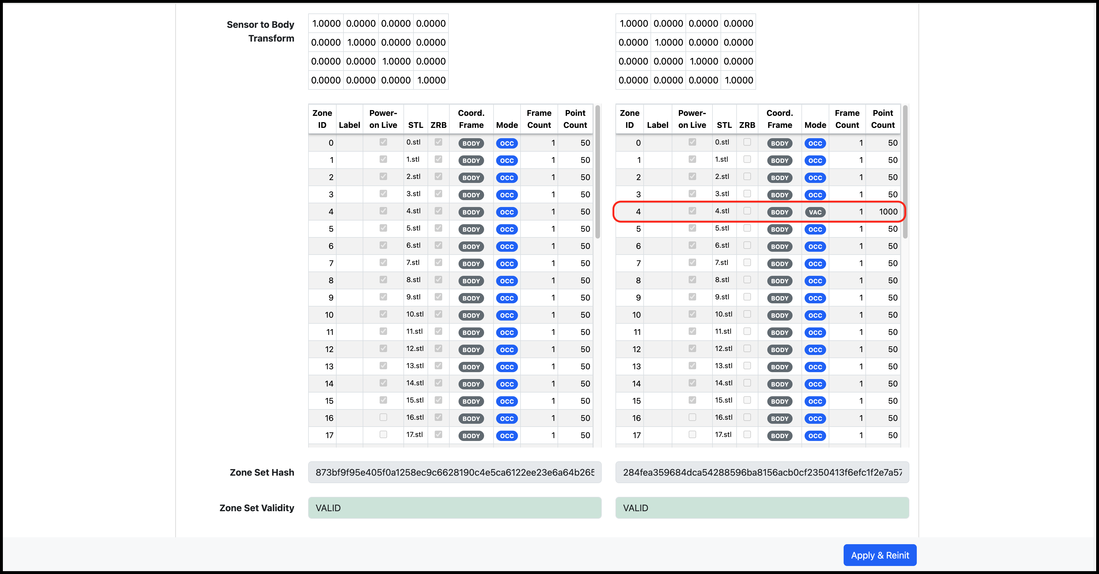
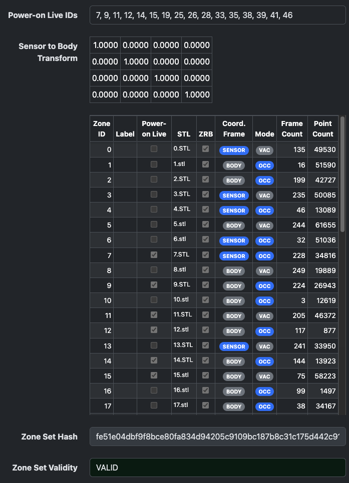
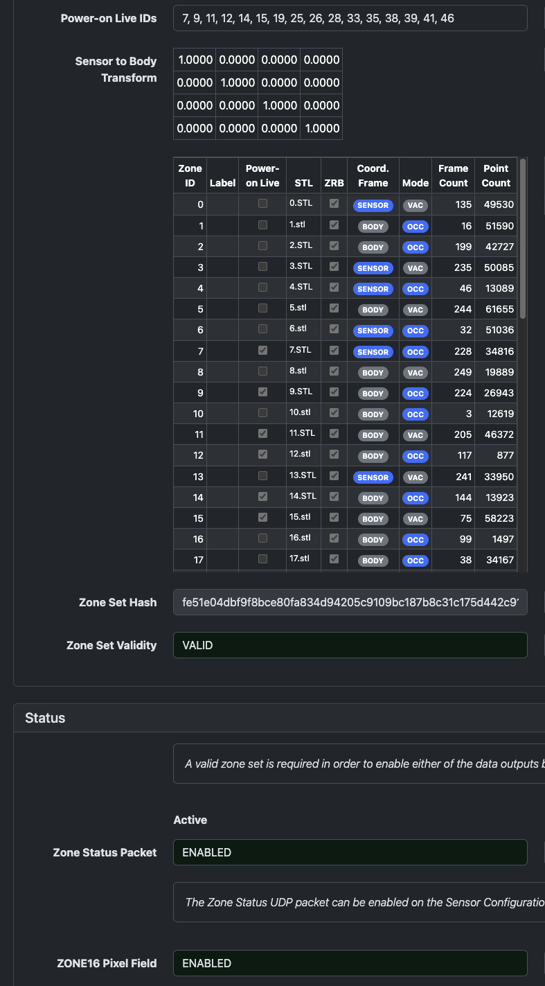
Configuration Summary
When a Zone Set Configuration passes sanity checks, the web UI displays the active configuration details.
ZRB File Format
The Zone Render Binary (.zrb) format stores sensor-rendered zone bounds. It is designed to be:
- Traceable: consistent with the original user inputs.
- Auditable: parseable into a visual output.
- Performant: fast for the sensor to load.
ZRB files include integrity checks that bind them to the user inputs, sensor configuration, and optical characteristics. On boot, the sensor verifies ZRB integrity using hashes.
Enabling Zone Monitor
A valid Zone Set Configuration is required before Zone Monitor can run. Once a valid configuration has been uploaded, Zone Monitor output is enabled by configuring one or both of the following:
- A ZONE16 lidar profile, such as
RNG15_RFL8_NIR8_ZONE16orRNG19_RFL8_SIG16_NIR16_ZONE16. - A Zone Monitor UDP destination address and port for Zone Monitor Update packets.
After enabling the outputs and applying the configuration, the sensor reinitializes. When it reaches the RUNNING state, it begins monitoring the configured live zones.
Note: If the sensor detects a misconfiguration before rendering, it reports an upfront error. If it detects a rendering-time misconfiguration, such as a zone that does not intersect the field of view, the sensor transitions to the
HALTEDstate.
Validating Operation
After applying a Zone Set Configuration:
- Query the rendered ZRBs and visualize them in the SDK to confirm field-of-view coverage, geometry, and orientation.
- Record the sensor-calculated Zone Set hash.
- If Zone Monitor UDP packets are enabled, verify that the packet hash matches the recorded Zone Set hash.
- Verify that the expected Zone IDs are being monitored.
Note: Zone IDs are not directly encoded in lidar pixels. ZONE16 lidar profiles use a bit flag to indicate whether a pixel is inside each monitored live slot. The user controls which Zone ID is assigned to each slot.
When changing the live set through API calls, monitor the Zone Monitor Update packets to verify that the updated Zone IDs are reflected. The UDP packets typically reflect the new live zones one or two frames after the command is received.
Expected Sensor Behavior
When Zone Monitor is enabled:
- Zone Monitor Update UDP packets are transmitted immediately after each frame completes.
- Pre-rendered ZRB files are rejected unless they match the current sensor configuration, including serial number, internally derived transforms and constants, and resolution settings.
- ZRB files with checksums that do not match known values and file contents are rejected.
- Rendering is aborted if any defined zone does not intersect the sensor field of view. This can catch azimuth masking, incorrect extrinsics, or mismatched STL coordinate frames.
- Zone Monitor does not start without a valid Zone Set Configuration.
Output Products
Zone Monitor provides two output products:
- Zone Monitor Update UDP packets report trigger status and statistics for up to 16 live zone slots.
- ZONE16 lidar profiles add a 16-bit per-pixel field that indicates which live zone slots contain the pixel.
Zone Monitor Update UDP Packet
Each update packet contains 16 zone slots. User-selected live zones are sequentially packed at the beginning of the structure. Each slot reports trigger status and statistics for one live zone.
Use the packet hash and Zone IDs to verify that alerts correspond to the expected active Zone Set.
Zone metadata provides context for trigger interpretation:
- Elevated occlusion count may indicate that the sensor window is contaminated or that the zone is obstructed.
- Point count and range data can help estimate the size and proximity of triggering objects.
- Triggered frame count provides hysteresis and short-term trigger history.
- A sudden increase in invalid points for a ground-facing sensor may indicate that the sensor mount has shifted and the sensor is pointing toward the sky.
Packet Header
Measurement Header
Zone Data
The following data repeats for each of the 16 zone slots, regardless of whether there is a live zone being monitored in that slot. Fields for inactive slots are all zeros (except for Zone ID, which is a reserved value).
Packet Footer
ZONE16 Lidar Profiles
ZONE16 lidar profiles add a 16-bit per-pixel field that identifies which live zone slots contain the pixel. This is useful for:
- Highlighting points in the point cloud that encroach on a defined zone.
- Filtering the point cloud to reduce downstream processing.
- Validating zone geometry against the rendered point cloud.
Trigger Definition
Zone triggers are based on three parameters:
- Trigger Type: occupancy or vacancy.
- Point Count Threshold: point count required for a frame to be considered triggering.
- Frame Count Threshold: number of consecutive triggering frames required before the zone status asserts.
A point is counted as inside a zone when its range is within the boundaries defined by the ZRB lookup table. Specifically, the range must be greater than or equal to the near range and less than or equal to the far range.
For each frame, all pixels are checked against the zone’s lookup table:
- An occupancy zone has a triggering frame when the point count meets or exceeds the Point Count Threshold.
- A vacancy zone has a triggering frame when the point count is below the Point Count Threshold.
- The zone status becomes triggered when the number of consecutive triggering frames meets or exceeds the Frame Count Threshold.
Statistics
Triggering Statistics
Triggered Frames: A saturating count of consecutively triggered frames. The count resets when the trigger condition deasserts.
Point Counting Statistics
Zone Count: A saturating count of the total points currently inside the zone. This count updates every frame, regardless of trigger status.
Occlusion Count: A saturating count of valid points detected below the configured near-bounds range, indicating potential occlusion.
Max Count: A precomputed value representing the total number of pixels monitored by the zone. This is calculated during rendering and stored in the ZRB.
Invalid Count: A saturating count of monitored pixels with zero range. This includes non-detections, invalid data from errors, skipped columns, and pixels excluded by azimuth masking.
Range Measurement Statistics
Min Range: Minimum detected range of points inside the zone.
Max Range: Maximum detected range of points inside the zone.
Mean Range: Average range of points inside the zone.
All range statistics are reported with an underlying resolution of 1 mm per LSB and an effective resolution of 8 mm.