

Multi-Sensor Synchronization
Multi-Sensor Synchronization
Phase Lock
Phase locking forces the sensor to cross a specific azimuth angle at a fixed fraction of each second—at the top (any mode), 1/10 s (1024x10 Hz), or 1/20 s (1024x20 Hz). The control loop runs at 1000 Hz. Phase locking synchronizes sensors with cameras, radar, and other lidars.
Before enabling phase lock, time-synchronize the sensor from an external source and set timestamp_mode to either TIME_FROM_PTP_1588 or TIME_FROM_SYNC_PULSE_IN.
Phase Locking Reference Frame
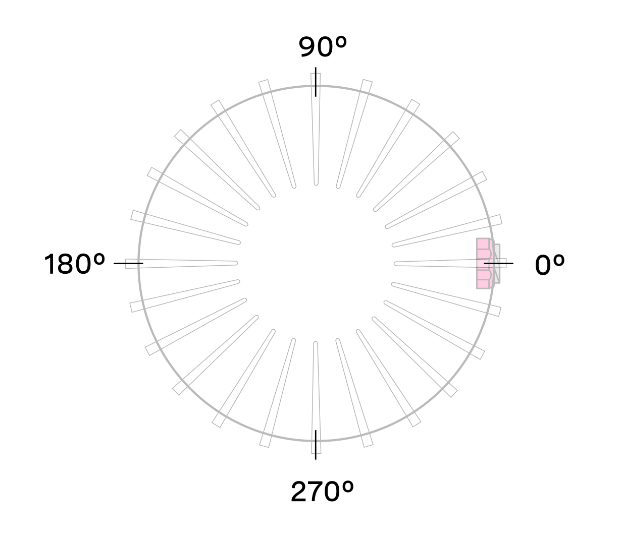
Phase lock offsets are specified in millidegrees in the Lidar Coordinate Frame. Angles increment counterclockwise when viewed from above:
- 0° towards the external connector
- 90° a quarter turn counterclockwise from the connector
- 180° opposite the connector
- 270° three quarter turns counterclockwise from the connector
Phase Locking Commands
- Enable or disable phase lock (default:
false):
- Set the phase lock offset angle (default:
0; valid range:0–360000millidegrees):
Multi-sensor Example
This example phase-locks three sensors on a vehicle so all point forward simultaneously. Each sensor’s connector faces a different direction.
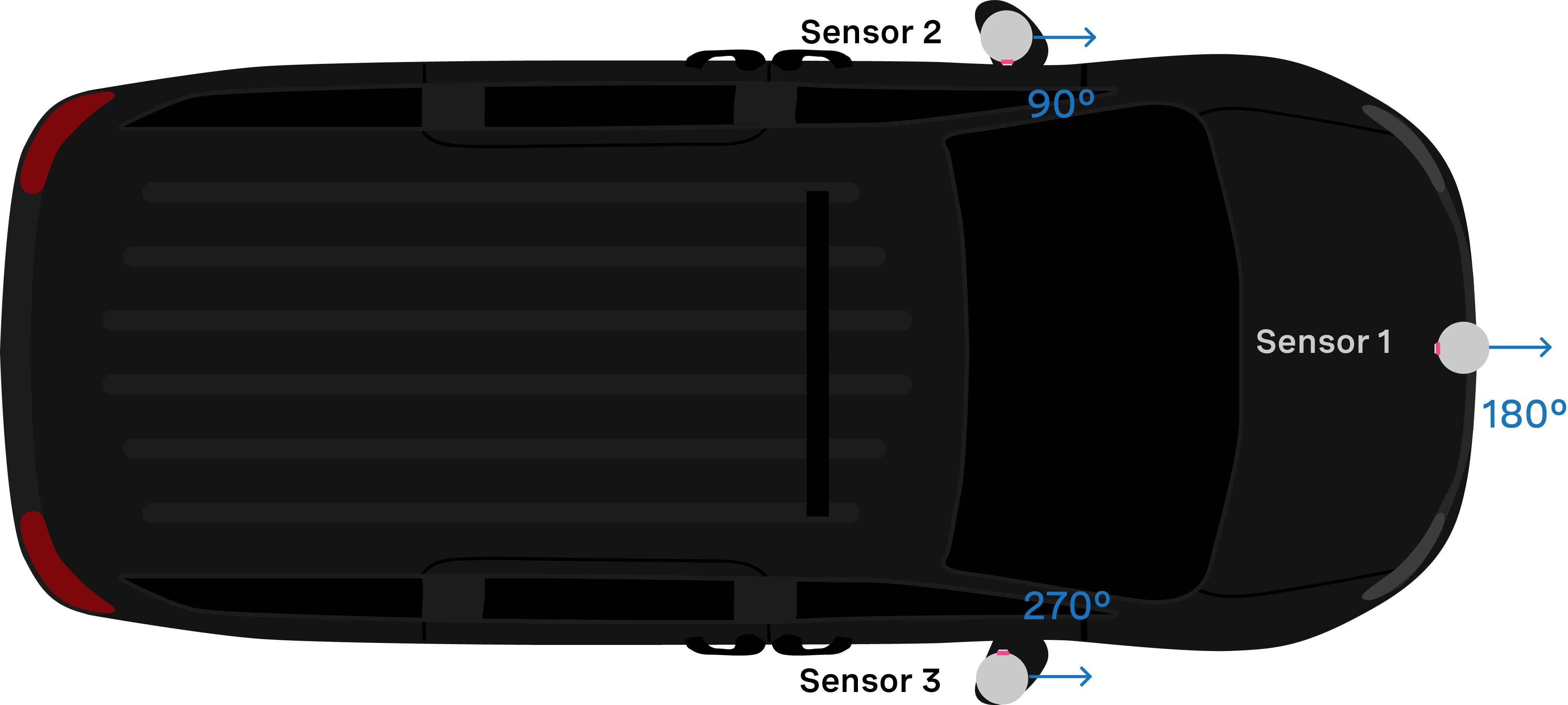
With all three sensors time-synchronized via an external source, use the following commands to align them forward simultaneously.
- Set Sensor 1 to phase lock at 180°:
- Set Sensor 2 to phase lock at 90°:
- Set Sensor 3 to phase lock at 270°:
Accuracy
Expected phase lock angular accuracy under normal operating conditions:
Phase Locking Alerts
The following alerts indicate phase locking errors. For a complete list, see alerts-and-errors in the Appendix.
Note: For information on how to mitigate crosstalk between different Ouster lidars in the same system refer to crosstalk-mitigation section of this manual.
Inter-sensor Interference Mitigation
Crosstalk occurs when two nearby sensors detect each other’s laser pulses as valid returns. Mitigate it with two steps:
- Phase lock the two sensors
- Set azimuth window on each sensor so that they don’t send data when they are pointing at each other
Two Sensor Example
This example mitigates crosstalk between two sensors mounted on a vehicle, both with connectors facing the rear.

A physical barrier between sensors is the most effective crosstalk mitigation and should be the first option considered. Where a barrier is impractical, use phase locking to eliminate the problem. Crosstalk only occurs when one sensor’s laser enters another sensor’s window. Phase locking forces both sensors to face each other at the same time, so crosstalk coincides with a period when neither sensor is collecting useful data.
-
Time-synchronize both sensors via an external source. See the Time Synchronization page for GPS or PTP options.
-
Phase-lock both sensors so they face each other simultaneously. In this example, Sensor 1 locks at 90° while Sensor 2 locks at 270°.
Note: In the examples below, to distinguish between the command and expected response, a dash has been added before the expected response. The actual response will be without the dash.
Example: Set Sensor 1 to phase lock at 90°:
- Step 1: Set “phase_lock_enable” to
true
- Step 2: Set “phase_lock_offset” to
90000
Example: Set Sensor 2 to phase lock at 270°:
- Step 1: Set “phase_lock_enable” to
true
- Step 2: Set “phase_lock_offset” to
270000
- Configure the azimuth window for both sensors. The region of interest for Sensor 1 is and for Sensor 2 is .
The calculation for and is:
If the two sensors are placed 100 mm apart:
Set an azimuth window of 282° for each sensor to prevent data transmission in the 78° where they face each other. Sensor 1’s window is the 282° centered around 270°. Sensor 2’s window is the 282° centered around 90°.
Sensor 1’s azimuth window starts at 129° and follows the CCW direction to end at 51°:
Example cURL command:
Example HTTP command:
Sensor 2’s azimuth window starts at 309° and follows the CCW direction to end at 231°:
Example cURL command:
Example HTTP command: